Theoretical Context
Newton’s laws of classical mechanics apply in inertial reference frames, i.e. frames that do not accelerate. However, in plenty of scenarios we are dealing with a non-inertial reference frame. In this simulation, we will consider one type of non-inertial reference frames: rotating frames. These frames exhibit fictitious forces, which are the non-physical but result from the mere fact that the frame is rotating instead. Upon consistently including those fictitious forces, we can write down the analog of Newton’s laws in rotating frames. Below, we set the mass of the particle to unity (m\equiv 1).
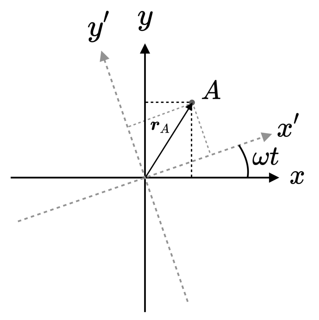
We consider an inertial, non rotating, frame (IF) characterized by coordinates \{x,y,z\}. The non-inertial rotating frame (NIF) is characterized by \{x',y',z'\}. At t=0 both frames coincide. The NIF rotates anti-clockwise at angular velocity \boldsymbol{\omega}=\omega\hat{z}, where the magnitude is \omega>0. See the schematic below. An arbitrary point A, the corresponding position vector \boldsymbol{r}_A and coordinate decomposition in both frames is shown as well. Note that the vector \boldsymbol{r}_A is the same in both frames, only the coordinates \{x_A,y_A\} and \{x'_A,y'_A\} are different. The z-coordinate is irrelevant here (and in any case we have z=z' in this setup).

As a shorthand notation, we denote the unit vectors in both frames as \boldsymbol{e}_i and \boldsymbol{e}'_i where i=\{x,y,z\}, so that e.g. \boldsymbol{e}_x=\hat{x}. The position vector can then be written as:
\begin{equation*}
\boldsymbol{r}=\sum_i r_i\boldsymbol{e_i}=\sum_i r'_i\boldsymbol{e}'_i,
\end{equation*}
where we will use the summation convention over repeated indices and leave out the \Sigma_i symbols from now on. The components are denoted by r_i, so that e.g. r_x=x. Note that the unit vectors of the IF are time independent, but those of the NIF are rotating, so that their time derivatives are:
\begin{equation*}
\dot{\boldsymbol{e}}_i=0,\quad\quad\quad\dot{\boldsymbol{e}}'_i = \boldsymbol{\omega}\times \boldsymbol{e}'_i.
\end{equation*}
Consequently, the velocities as measured in the two frames are different. From the taking the time-derivative of the relation r_i\boldsymbol{e_i}=r'_i\boldsymbol{e}'_i, we find:
\begin{align*}
\frac{d}{dt}(r_i\boldsymbol{e}_i)&=\frac{d}{dt}(r'_i\boldsymbol{e}_i')\\
\dot{r}_i\boldsymbol{e}_i&=\dot{r}'_i\boldsymbol{e}_i' + r'_i\dot{\boldsymbol{e}}'_i\\
\dot{r}_i\boldsymbol{e}_i&=\dot{r}'_i\boldsymbol{e}_i'+ r'_i(\boldsymbol{\omega}\times \boldsymbol{e}'_i)\\
\boldsymbol{v}&=\boldsymbol{v}'+ \boldsymbol{\omega}\times \boldsymbol{r}
\end{align*}
where we have identified \boldsymbol{v}=\dot{r}_i\boldsymbol{e}_i and \boldsymbol{v}'=\dot{r}_i'\boldsymbol{e}_i'. The difference between the two is exactly the relative velocity between the two frames.
Differentiating the above relation once more with respect to time, we obtain the acceleration relation:
\begin{align*}
\boldsymbol{a}&=\boldsymbol{a}'+2\boldsymbol{\omega}\times \boldsymbol{v}'+\boldsymbol{\omega}\times (\boldsymbol{\omega\times\boldsymbol{r}})+\dot{\boldsymbol{\omega}}\times \boldsymbol{r}\\
&=\boldsymbol{a}'+2\boldsymbol{\omega}\times\boldsymbol{v}-\boldsymbol{\omega}\times(\boldsymbol{\omega}\times \boldsymbol{r})+\dot{\boldsymbol{\omega}}\times \boldsymbol{r},
\end{align*}
where the first and second line are written in terms of velocities as measures in the NIF and IF, respectively. The additional terms correspond to the following fictitious forces:
- Coriolis Force. The term 2\boldsymbol{\omega}\times\boldsymbol{v}' corresponds to the Coriolis force.This force only exists when the particle is not stationary.
- Centrifugal Force. The term \boldsymbol{\omega}\times (\boldsymbol{\omega\times\boldsymbol{r}}) corresponds to the centrifugal force.
- Euler Force. The term \dot{\boldsymbol{\omega}}\times\boldsymbol{r} corresponds to the Euler force and only exists in a frame that is rotating at an accelerating pace, i.e. \dot{\omega}=0.
Rolling Ball on Merry-Go-Around
We will apply the formalism above to a merry-go-around situated in the (x,y) plane rotating at constant angular velocity \boldsymbol{\omega}=\omega\hat{z}, so that \dot{\omega}=0. We have three observers (A, B and C) of which A and B are stationary on the rotating merry-go-around and C is located next to it. The former observers (A,B) are located in the non-inertial frame of the merry-go-around, the latter (C) observer defines an inertial frame. In the NIF of the rotating merry-go-around, a ball is rolled radially outwards in the \hat{x}' direction from observer A to B at constant velocity, so that:
\begin{equation*}
\boldsymbol{r}'_b(t)=\boldsymbol{v}_b' t=v_b't\;\hat{x}'.
\end{equation*}
In this case, we have \boldsymbol{a}'=0, so that the acceleration of the ball as measured by observer C in the IF is:
\begin{equation*}
\boldsymbol{a}=2\boldsymbol{\omega}\times\boldsymbol{v}-\boldsymbol{\omega}\times (\boldsymbol{\omega}\times\boldsymbol{r}).
\end{equation*}
Since the motion is confined to the (x,y) plane, we can write \boldsymbol{r}=x\hat{x}+y\hat{y} and \boldsymbol{v}=v_x\hat{x}+v_y\hat{y}. Evaluating the cross products, we find:
\begin{equation*}
\boldsymbol{a}=2\omega(v_x\hat{y}-v_y\hat{x})+\omega^2\boldsymbol{r}.
\end{equation*}
Writing the above equation in terms of the respective components, we obtain:
\begin{align*}
\ddot{x}+2\omega v_y-\omega^2 x &=0,\\
\ddot{y}-2\omega v_x-\omega^2 y &=0.
\end{align*}
Defining the auxiliary variable q\equiv y+ix , we can combine them into:
\begin{equation*}
\ddot{q}+2i\omega\dot{q}-\omega^2q=0.
\end{equation*}
The strategy will be as follows. We solve this differential equation for q using the appropriate initial conditions. Then, then trajectory of the ball is readily obtained from y=\mathrm{Re}(q) and x=\mathrm{Im}(q) . We start with the ansatz q(t)=C e^{kt}. The characteristic equation for the exponential factor k then reads:
\begin{equation*}
k^2+2i\omega k-\omega^2 =0,
\end{equation*}
which gives only one solution, k=-i\omega. The solution is then:
\begin{equation*}
q(t)=c_1 e^{-i\omega t}+c_2t e^{-i\omega t}.
\end{equation*}
We set the initial conditions at t=0 by writing q_0=y_0+ix_0 and \dot{q}_0=v_{y,0}+iv_{x,0}, which imposes the constants to be:
\begin{equation*}
c_1=q_0,\quad\quad\quad c_2=\dot{q_0}+i\omega q_0.
\end{equation*}
In principle, this provides the full solution to the motion of the ball (i.e. its trajectory) in the IF.
Simulation
The simulation shows two panels, the left panel shows the system from the perspective of observer C in the IF. The right panel shows the system from viewpoint of A and B in the NIF. The observers are indicated with grey dots, and the line of sight of observer A is indicated in dark blue to illustrate that A rotates along with the merry-go-around. That is, observer A faces observer B at the edge at all times. The ball and its trajectory are in red. The net acceleration and the components due to Coriolis and centrifugal force are included as well in the left panel. The centrifugal force pushes the ball outwards, while the Coriolis force forces it to bend in a counterclockwise direction. In the right panel, there is no net force acting on the ball, but observer C appear to follow circular motion, with an associated centripetal force (denoted in green).